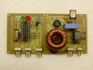
- 12 Volt Sump Pump Control:
- 12 Volt Toilet Tank Refiller:
- Circuit checks swamp cooler water level: 10/31/2002 EDN - Design Ideas / A "swamp cooler" is an easy way to obtain effective air conditioning, especially in hot and dry climates, if a water source is readily available. Although most units are very reliable, the storage-reservoir control usually uses a single level-detector component. Failure of this component can lead to serious water damage..
- Digital Water Wave/Tide/Level Meter (PIC16F876):
- Simple Emergency Sump Pump Control: Sump Pump Control for12V DC Bilge Pump
- Water Activated Alarm:
- Water Level Alarm:
- Water Level Controller:
- Water Level Indicator With Alarm:
- Water Level Sensor:
- Water-Level Controller:
- Water-Level Sensor Uses Hysteresis: 08/21/00 Electronic Design - Ideas for Design / A low-voltage electronic circuit that senses upper and lower water levels is often used for alarms and sump-pump activation. Since an electronic sensor has no moving mechanical parts, it eliminates problems with corrosion and wear and tear. The. . .
- Waterpump Safety Guard for Fish-pond:
Thursday, March 23, 2006
Water Level Monitors
Monday, March 20, 2006
Tachometers / RPM Circuits
AN-162: LM2907 Tachometer/Speed Switch Building Block Applications: National Semiconductor - Application Note |
| Digital Tachometer Avoids Analog Vices: 11/10/94 EDN-Design Ideas / The digital tachometer in Fig 1a is a component of the digital seek servo loop in Fig 1b. The loop produces an error signal that causes a motor to follow a sophisticated velocity profile (Fig 2). Although you could use an analog tachometer, the digital one costs less, performs better, is less sensitive to temperature, and implements easier in a custom IC.... |
| LM2907 Tachometer/Speed Switch Building Block Applications: National Semiconductor - Application Note |
Saturday, March 11, 2006
Programmable Digital Ignition
Two Stroke CDI (Capacitive Discharge Ignition)
The next schematic shows the coil configuration at magnetic plate and the position of the pick-up at the outer sider of the plate. This pick-up is triggered by the step on the plate. Below are shown the signals measured by means of an oscilloscope at the output of the magetic plate, and the output of CDI for the primary of the HV coil.
detail
READ MORE -
Programmable Digital Ignition
The next schematic shows the coil configuration at magnetic plate and the position of the pick-up at the outer sider of the plate. This pick-up is triggered by the step on the plate. Below are shown the signals measured by means of an oscilloscope at the output of the magetic plate, and the output of CDI for the primary of the HV coil.
detail
Thursday, March 02, 2006
Programmable CDI Ignition with PIC16F84

Features::
-As simple as possible
-Programmable advance control
-Use no exotic hard-to-find components
-Use a normal 4.8V RX battery
-Integrated spark test function, no signal generator is needed.
(makes 4 or 140 sparks/second without the need for a trigger input)
-Spark control can be separated from the voltage board
(to be used as a front end for a CDI without advance)
-Integrated strobe light
-May be extended with a failsafe/engine stop module. (not designed yet)
for more information visit this site
Subscribe to:
Comments (Atom)